Products
Magnetron transmitters with spatial-harmonic magnetrons with secondary-emission cathode and hard-tube modulator were developed to be used in stationary equipment like 95 GHz and 36 GHz cloud Doppler radars. Characteristics of 95 GHz and 36 GHz transmitters are given in the Table. The operation of the transmitters is controlled by a microprocessor, which provides a smart mode of transmitter operation. In particular, pulse-to-pulse programmable control of pulse duration and pulse repetition frequency is introduced. Local and remote control of the transmitters are possible.
The transmitters include the following main parts: a high-voltage power supply, filament power supplies for the magnetron and the modulator tube, a driver for this tube and a controller. The low voltage power supplies were built by using resonant technique to provide high efficiency and to suppress interference. The high voltage power supply utilizes a flyback converter with a current feedback along with a voltage multiplier. Such scheme allows one to obtain the voltage ripple as low as 2V with the output voltage of 20 kV and the output power of 500 W. The output stage of the hard tube driver is based on the two-pole scheme and provides voltage swing of 1500 V with the rise and fall time less than 15 ns. All power supplies in the modulator are synchronized at frequencies multiple to the pulse repetition frequency of the transmitter.
The transmitters produce the output pulses with a good shape, a negligibly small jitter, and the pulse-to-pulse frequency relative variations less than 10-8. The intrapulse phase deviation does not exceed 10° and 20° for 36 and 95 GHz transmitters, respectively, with the pulse duration of 400 ns.
Typical build-up of the RF pulses of 95 GHz transmitters is shown in a photo in Fig. 1. This photo was obtained by superposition of 20 000 successive pulses. Easy to see that the pulse jitter is less than 2 ns. The jitter occurs only at the initial stage of the pulse formation. A photo on the right of Fig. 2 illustrates power spectrum in logarithmic scale for the same train of pulses. The level of the first "frequency sidelobe" is about -30 dB, and the spectrum width (between the two first minima) is 2/T, where T is the pulse duration.
| Frequency, GHz | 36 | 95 |
| Peak output power, kW | 30 | 4 |
| Pulse duration, ns | 50-500 | 50-400 |
| Duty cycle (max) | 0.005 | 0.005 |
| Cooling | Water | Water |
| Weight, kg | 25 | 25 |
| Power supply, V | 220 AC | 220 AC |
| Power consumption, W | 700 | 500 |
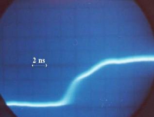 Fig. 1. Build-up of RF pulses of 95 GHz, 4 kW transmitter.
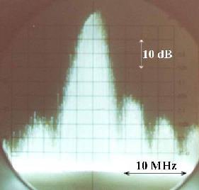 Fig. 2. Power spectrum of output pulses of 95 GHz, 4 kW transmitter.