Products
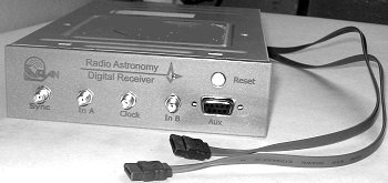
Two-channel digital receiver which is used for observing both stationary and sporadic radio sources in the decameter wave band. The ADC module is manufactured as a separate block in order to avoid interferences from the DSP board and the PC electric circuits. Due to this and other solutions, both a high SFDR value and a low level of the noise floor have been achieved.
Receiver characteristics are listed below:
- Sampling frequency is of 66 MHz.
- Regimes: waveform capture, spectrogram analysis, coherence analysis (cross covariance between the two inputs).
- The ADC module is manufactured as a separate block to avoid interferences from the DSP board and the PC.
- Connection via a 2x2.5Gbit/sec serial data link.
- PCI-X64/66 standard interface for the communication with the PC.
- High SFDR value (115dBc) and a low noise floor (-120dBFS)
- Real-time RFI mitigation option.
- Client-Server architecture of the interactive software controls the receiver (modes of operation, processing parameters) remotely via Internet in real time.
 |
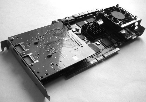 |
| ADC module | DSP board |
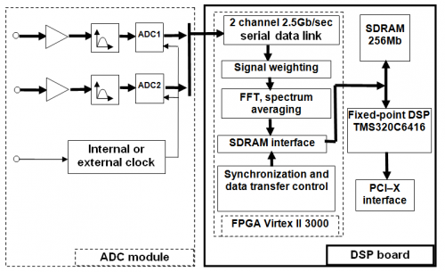
Physically, the digital receiver consists of two parts (see figure above): an ADC module and a DSP board connected via a 5Gbit/sec serial data link. In the ADC module, the LTC2208 A/D converters are used. The DSP board is designed on the base of the Xilinx Virtex-II 3000 as the FPGA and, in addition, it has the fixed-point signal processor TMS320C6416 and a 256 Mbyte SDRAM. The DSP board is produced as a PCI extension card which supports the PCI-X64/66 standard interface for the communication with the PC. Different modes of signal processing can be realized in the receiver by using the FPGA and the signal processor capabilities.
It is well known that the negative impact of radio frequency interference (RFI) on the quality of data is a matter of increasing concern especially for the low frequency radio astronomy. In this band, man-made ground-based sources and/or low earth orbit (LEO) satellites produce very strong RFI, and non-linearity caused by the poor dynamic range will spread the interference over the whole spectrum. The automatic gain control does not help as introducing attenuation will decrease receiver sensitivity resulting in loss of the weak signal from astronomical sources. There is one way to overcome this difficulty: increase the linear dynamic range of a receiver and apply some RFI mitigating technique usually in spectral domain. Results of the laboratory receiver tests prove the high linearity and perfect flatness of the amplitude-frequency characteristics:
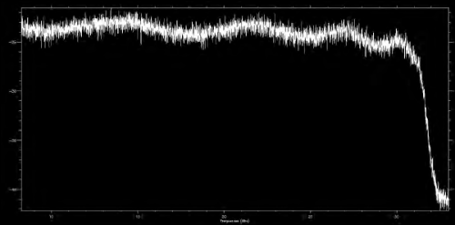 Frequency overshooting is <2dB in bandwidth 5 – 30MHzf
 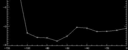 Linearity is <1dB over 100dB dynamic range
The ADC module is manufactured as a separate block in order to avoid interferences from the DSP board and the PC electric circuits. Due to this and other solutions, both a high SFDR value and a low level of the noise floor have been achieved. Generally, the SFDR parameter is the critical for the A/D converters used for radio astronomical observations, where weak celestial signals from astronomical sources should be detected on the background of powerful in-band man-made interferences. Therefore, serious efforts were undertaken to increase the SFDR value. Among them, an automatic digital DC bias compensation is introduced, and data dithering is carried out during transferring data to the DSP board via the serial link. Theoretical maximal SNR (or dynamic range) for 16-bit LTC2208 A/D converters is 78 dBFS while practically the value of 74 dBFS was achieved in the presented receiver that can be considered as a good result.
The elaborated receiver/spectrometer was optimized to have as high as possible maximal signal to noise ration (SNR) value (or dynamic range). To meet this request, high spurious free dynamic range (SFDR) value of 115 dBc and low level of the noise floor (–120 dBFS) have been achieved, as it can be seen from the table below, where receiver’s characteristics and data processing capabilities are presented:
| Number of the input channels | 2 |
| ADC sampling frequency, MHz | 10 … 130 |
| ADC resolution, bits | 16 |
| Input bandwidth, MHz | 1 … 60 |
| SNR/SFDR/ Noise floor (dBFS, dBc, dBFS) | 74/>115/ –120 |
| Effective number of bits (ENOB) | 12 |
| FFT size / resolution bits | 16384 / 30 |
| Real 16384-point FFT calculation time, µs | 57 |
| Number of the frequency channels | 8192 |
| Number of spectrum averaging | 1 … 1024 |
| Dyn. spectrum time res. (60MHz), ms | 0.125 … 127 |
| Waveform mode (Ch1, Ch2, Ch1&Ch2) | Yes |
| Spectrometer mode (Ch1, Ch2, |Ch1* Ch2|) | Yes |
| Correlation mode (Ch1, Ch2, (Ch1* Ch2)) | Yes |
Data processing
The particular configuration of the receiver data processing, which was used during the astronomical observation campaign at the decameter radio telescope UTR-2, is presented on figure below:
A real time, half-overlapped FFT calculation and spectral averaging are carried out in the FPGA of the DSP board. FFT is performed for 16384 points of a real signal (carrier) that provides 8192 frequency channels. For example, it gives 3.7 kHz resolution of the spectral line considering the signal input band with is limited to 30 MHz. To increase performance of the FFT calculation for real signals, a method of calculation of two real FFTs as a single complex FFT with the following data ordering is used. Weighting window coefficients with the 18 bits resolution are loaded into the DSP memory to be applied before the FFT.
The fixed-point, digital signal processor TMS320C6416 is used to control data transferring from the FPGA to the PCI controller. As a further possible improvement of the receiver, the signal processor along with the RAM memory as a buffer can be also used for the realization of an advanced analysis of the dynamic spectra in real time, for example, to realize a RFI mitigation techniques.
Along with the spectrum calculating and correlation modes, the DSP board can operate in a waveform mode, when raw data from the both input receiver channels are just transferred to the PC. In this mode, it is possible to transfer data permanently with the rate of 260 Mbyte/sec via the PCI-X64/66 interface and store the data on the HDDs organized as a RAID-0 system. Raw data (or waveforms) storing gives a useful opportunity to implement an intelligent signal analyzing technique in post-processing.
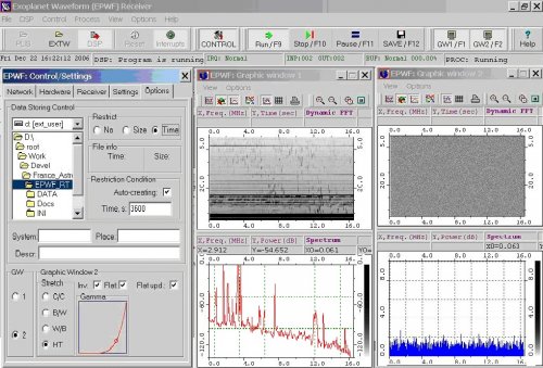
Control software
Dedicated software for control of the data acquisition system has been developed. Software is operating under the OS Windows’NT/2K/XP and provides a friendly graphic user interface, to manage the receiver hardware, and to control parameters of data processing, storing, and on-fly data displaying. In addition, software is organized as a network server, so, the network capabilities make the system more convenient in exploitation. For example, possibility of the remote control of the receiver is essential for the long-term unmanned astronomical observations when the autonomous mode of the data acquisition system operation is required
- HW, processing and data storing parameters control
- Real-time signal statistic analyzing
- Remote (network) control
- Script self-acting capability
- On-fly data displaying
Time synchronization
Radio astronomy observations performed on multi-beam radio telescopes may request for simultaneous operations of several receivers. In this case the receivers should be strictly synchronized. Moreover, for the interferometry task the receivers can be located far from each other. In this case absolute time synchronization of the data sampling is required. Described receiver has such time synchronization capability and it is successfully using on radio telescope UTR-2, where 5 receivers are operating simultaneously. Figure below describes the time synchronization of several receivers.
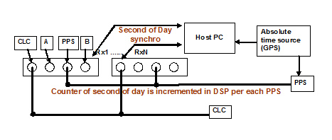
- DSP counter of absolute second of day is synchronized with PC at the beginning of the operation
- Start of ADC sampling at a “target time” is performed using PPS signal from GPS
- The time marker inserted into data after each 16384-th sample (without samples losses)
- Time marker contains: the second of day and “phase” of the second (number of ADC CLC cycles starting from second begin)