Products
The antenna system consists of four independent slotted waveguide sections shown in Fig. 1 together with a radar T/R-module. Each antenna section forms the radiation pattern with the beamwidth of 10° in the elevation plane and 2° in the azimuth plane. The antenna beams are displaced with the step of 16° in the elevation plane providing the total observation sector of about 60° as indicated in Fig. 2
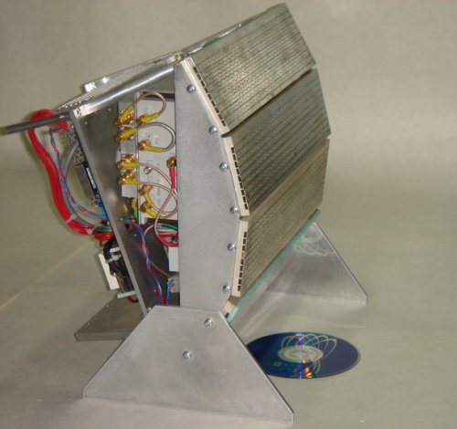 Fig. 1. Ka-band Slotted Waveguide Antenna
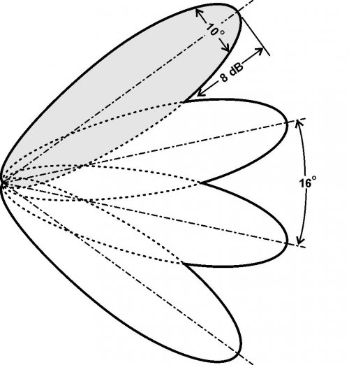 Fig. 2. Ka-band Slotted Waveguide Antenna Operation Mode
Each antenna section is protected from moisture and dust with a simple cap (not shown in Fig. 1) made of laminated foam polystyrene.The sections are switched electrically by using an original high power reciprocal SP4T switch based on P-i-N diodes. The switch is based on three waveguide Y-junctions connected as a binary tree. The maximum peak power for such configuration is as high as 2.5 kW with the switching time as low as 1 μsec. The bandwidth of the switch is about ±3 %.
Antenna Characteristics
| Operating bandwidth, GHz | 0.4 (in Ka-band) |
| Beam type | fan |
| 3dB beam width in E-plane, deg | 10 |
| Observation sector in E-planes, deg | 60 |
| 3dB beam width in H-plane, deg | 2 |
| Polarization | Linear/Vertical |
| Side lobes level, dB | <-22 |
| Gain, dB | >31 |
| VSWR | <1.2 |
| Antenna section switching time, μsec | 1 |
| Dimensions of each antenna section, mm | 310 x 70 x 8 |
| Weight, kg | 0.3 |