Products
Radar Overview
The purposes of the surveillance and tracking radar are:
- Detection of air targets and measurement of their coordinates and RCSs,
- Tracking of a chosen target with continuous measurement of the target coordinates and velocity.
The surveillance and tracking radar is a monopulse, all-weather radar with mechanical beam steering. It works in a pulse regime, and a coherent FFT-based signal processing is utilized. The radar antenna is protected by a radom.
The radar is equipped with a clutter suppression system and with a Kalman filtering scheme for trajectory calculation and extrapolation. The system operation is fully controlled by a radar operator through a Windows-based GUI.
The radar system composition:
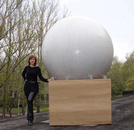
- antenna mounted on a elevation-over-azimuth pedestal (see Fig. 1),
- equipment rack,
- operators computer.
The radar can be installed on a movable platform or in a light-weight trailer. The radar operator with the radar computer can be located distantly from the radar.
 Fig. 1. Antenna covered by radom with elevation-over-azimuth pedestal
Radar Specifications
| Carrier frequency | Ku-band |
| Pulse power | 20 kW |
| PRF | 1-10 kHz |
| Pulse width | 0.3 - 5.0 msec |
| Antenna aperture | 1.0 m |
| Beam width | 1.6° (-3 dB one-way) |
| Azimuth range | 180° |
| Elevation range | -5° - +85° |
| Maximal azimuth and elevation slew rate | 100°/s |
| Maximal azimuth and elevation acceleration | 100°/s2 |
| Range resolution | 45-150 m (depending on pulse width) |
| Range accuracy | 15 m |
| Maximal detection range | 150 km (for RCS of 1 sq.m) |
| Monopulse measurement accuracy | 0.05° |
| Clutter cancellation ratio | 40 dB |
| Target data updating | 1 kHz |
| Maximal power consumption | 5 kW (220 V, 50 Hz) |
Dimensions and weight:
| Dimensions | |
| Antenna with radom, servo, pedestal | 2800x1980x1980 mm cubed |
| Equipment rack | 960x550x600 mm cubed |
| Weight | |
| Antenna with radom, servo, and pedestal | 420 kg |
| Equipment rack | 95 kg |
Illustration of radar operation:
In the AVI file (or, you may download a zipped archive), radar operation is illustrated by a movie which is taken from the monitor of operator's computer during real radar operation. The monitor shows radar control panels and three windows. The left window shows the plan-position indicator which indicates targets position in the coordinate azimuth-range, target height (figure near the green point), projection of the target position on the Earth surface (the green point). The upper window on the right shows targets position in the coordinates elevation-range. The red line in the both windows is instant position of the antenna beam. The lower window on the right shows a normalized level of target signal in dB on the range coordinate.
After initialization of the attached program, several separate fragments of radar operation can be observed. At the beginning, the radar performs scanning in the elevation direction. At some moment, a target has appeared at the range of about 10 km (instant target coordinates are given in the left bottom corner). This target has been automatically captured for the following tracking. Some fragments of the tracking are shown, a possibility of the target trajectory zooming is illustrated. The last fragment of the movie shows the last stage of the target tracking when the target was at the distance of about 100 km.
