Products
A dual 95 and 36 GHz side-looking airborne radar system for remote sensing applications has been developed in cooperation with the Technical University Hamburg-Harburg and Moscow State Technical University. The general characteristics of the radar system are as following:
| Transmitted frequencies, GHz | 36-/+ 0.5 | 95-/+ 0.5 |
| Peak transmit power, kW | 20 | 4 |
| Pulse length, ms | 0.05-0.4 | 0.05-0.4 |
| Pulse repetition frequency (max), kHz | 5 | 5 |
| Receiver noise figure, dB | 6 | 9 |
| Tilt angles, deg | from 30 to 70 | from 30 to 70 |
| Beam width in azimuth plane, deg | 0.5 | 0.5 |
| Polarisation | Vertical | Vertical |
| Resolution in the flight perpendicular direction | Better than 30m | Better than 30m |
| Resolution in azimuth direction (from the flight altitude of 4 km) | Better than 60m | Better than 60m |
| Width of the instantly observation area (from the flight altitude of 4 km) | 8.5km | 8.5km |
| DC supply voltage, V | 28 | |
| Watt consumption, W(max) | 1300 | |
| Total weight | 70kg | |
| Flight conditions | ||
| Maximum aircraft speed, m/sec | 300 | |
| Maximum altitude, km | 8 | |
Geometry of the observation is illustrated in fig 1.
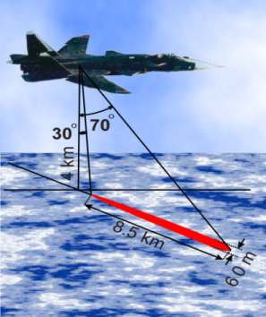 Fig. 1. Geometry of the observation.
Possible applications of the radar system
- Investigation of the radar scattering properties of various surfaces at millimeter wavelengths;
- Pollution monitoring;
- Detection of oil spills on water surface;
- Mapping;
- Determination of soil moisture;
- Monitoring of the water level of rivers and dynamics of flood;
- Monitoring of vegetation;
- Detection of leakage from channels and dams.
Radar system description
The radar system consists of the 3 and 8 mm wave channels with corresponding antennas, transmitters, receivers, and signal pre-processing units. A single interface unit and a host computer are used for both channels.
General view of the radar system installed on a helicopter is shown in Fig. 2. Due to small dimension of the radar, it is possible to install it just in an open door of the helicopter.
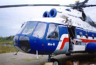 Fig. 2. The dual-frequency radar system installed on a helicopter.
An example of a real-time image of an observation area produced by the radar is shown in Fig. 3.
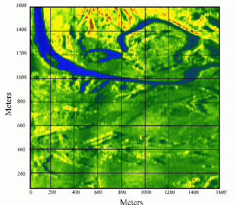
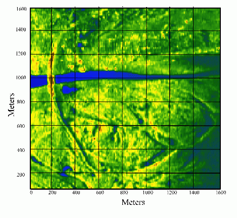 Fig. 3. Examples of a real-time radar images of an observation area.
The radar system can be effectively used for detecting oil spills on river and lake surfaces. Examples of optical and radar images of an oil spill on river surface are shown in Fig. 4 and 5.
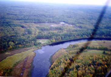 Fig. 4. Optical image of an oil spill on Vetluga river.
 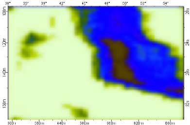 Fig. 5. Radar image of the oil spill.