Products

The radar (produced in cooperation with METEK, Germany) is designed for unattended long-term operation to provide real-time permanent measurements of vertical profiles of cloud reflectivity, mean velocity, velocity variance, and velocity spectrum. A possibility of raw data saving is also introduced. A permanent calibration system is included in the radar. The radar contains a server to provide remote control and data receiving. The server provides the possibility for a number of clients to get simultaneously real time radar data in a convenient form. A remote control of the radar operation is also made possible. Any network supporting the TCP/IP protocol, including the Internet, can be used to provide the above services.
The Radar Features
 |
|
The radar characteristics
The radar is intended for real time measurements, imaging, and storing of
- reflectivity profile,
- linear depolarization ratio (LDR) profile,
- velocity profile,
- velocity variance, and
- Doppler spectrum.
These quantities are accessible in real time in various graphical and map forms on computer displays of local and remote users. The complete raw data, which are digitized signals from the I and Q receiver channels, collected simultaneously from all heights can also be stored for a following analysis.
The radar measurements are performed with the following characteristics:
| Minimum Height | 200 m |
| Measuring Range | 15 km |
| Range Resolution | 15, 30, 45 and 60 m/sec |
| Doppler Velocity Resolution | 0.05 m/sec |
| Maximal Unambiguous Velocity | +/-15 m/sec |
| Number of Gates (max) | 500 |
| FFT Length | 128, 256 and 512 |
| Minimum Dwell Time | 0.1 sec |
| Antenna Beam Width | 0.6° x 0.6° |
| Sensitivity at 5 km (with the integration time of 0.1 sec) | -45 dBz |
The described radar operates in pulsed mode and utilizes a coherent-on-receiver technique for Doppler measurements. The main technical parameters of the radar are as following:
| Frequency | 36.5+/-0.5 GHz |
| Peak Power (max) | 30 kW |
| Tube Type | magnetron |
| Pulse Width | 100-400 ns |
| Pulse Repetition Frequency | 2.5, 5, and 7.5 kHz |
| Minimum Detectable Signal | -104 dBm |
| Polarization Decoupling | -40dB |
| Sampling Rate | 50 MHz |
| Sampling Resolution | 14 bit |
| Type of Bus for the Signal Processing Board | PCI |
| Operation System of the Host Computer | Linux or MS Windows |
| Network Protocol | TCP/IP |
| Antenna Diameter | 1 m |
| Sidelobe Level | -20dB |
| Power Supply | 230V+/-10% AC |
| Watt consumption | 1.3 kW |
| Weight | 140 kg |
The radar has a built-in permanent calibration system. The radar calibration is based on independent measurements of the transmitter and receiver parameters. For these purposes, the transmitter output power and receiver sensitivity are continuously measured.
A possibility of the measurements of the linear depolarization ratio (LDR) and the intensity and the Doppler spectrum of both co- and cross-polarized components of backscattered signals is introduced in the radar. The cross-polarization isolation is better than 40 dB.
The radar has network capabilities to allow for remote radar control and data receiving through any network supporting the TCP/IP protocol, including the Internet. In order to provide the network services, a special radar server is developed and introduced. The server is working on the radar host computer under control of the Linux operating system. There is also a software package of Windows programs for obtaining and visualising radar data via the Internet. Remote control and diagnostics of the radar operation from any network computer is made possible as well.

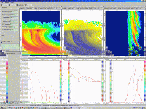
An example of configuration of the Image control page on the user display is shown in the figure above. The page includes a control panel and a data image panel. The control panel allows controlling radar operation in real time. On the data image panel, there are intensity, velocity, and spectrum windows. Each of these windows is divided into two subwindows. The upper part reflects the height-time map of intensity and velocity in the case of intensity and velocity windows, respectively. The lower part of these windows shows instant oscilloscope plots of the incoming data. The instant oscilloscope plots can display either the horizontal or the vertical cut of the upper maps. For example, such cut may show the intensity versus time at some selected height (horizontal plot), or the intensity versus height (vertical plot). The upper plot of the spectrum window is the dynamical spectrum, where vertical axis corresponds to time and horizontal one is the Doppler frequency (or corresponding velocity). The lower plot is an instant spectrum.
